TM-9-2320-440-13-P - Page 529 of 1616
TM 9-2320-440-13&P
0055-1
0055
FIELD LEVEL MAINTENANCE
CHASSIS AIR LINE REPLACEMENT
INITIAL SETUP:
REMOVAL
NOTE
•
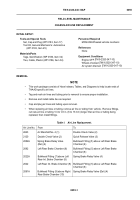
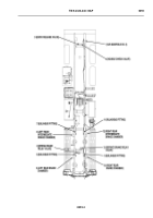
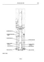
This work package consists of Hose Indexes, Tables, and Diagrams to help locate ends of
THAAD specific air lines.
•
Tag and mark air lines and tubing prior to removal to ensure proper installation.
•
Remove and install cable ties as required.
•
Cap and plug air lines and tubing upon removal.
•
When replacing air lines or tubing, remove air line or tubing from vehicle.
Remove fittings,
cut new air line or tubing 1/4 to 1/2 in. (6 to 13 mm) longer than air line or tubing being
replaced, then install fittings.
-
-
-
-
-
-
-
-
-
-
-
-
-
-
-
-
-
-
-
-
-
-
-
-
-
-
-
-
-
-
-
-
-
-
-
-
-
-
-
-
-
-
-
-
-
-
-
-
-
-
-
-
-
-
-
-
-
-
-
-
-
-
-
-
-
-
-
-
-
-
-
-
-
-
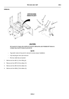
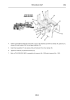
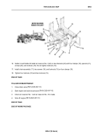
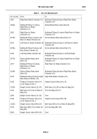
Table 1.
Air Line Replacement.
Air Line No.
From
To
2623
Air Manifold No. 4 (1)
Double Check Valve (2)
2120
Double Check Valve (2)
Quick Release Valve (3)
2082A
Spring Brake Relay Valve
(Del) (4)
Bulkhead Fitting (5) above Left Rear Brake
Chamber (6)
2082
Left Rear Brake Chamber (6)
Bulkhead Fitting (5) above Left Rear Brake
Chamber (6)
2022A
Bulkhead Fitting (7) above Left
Rear Int. Brake Chamber (8)
Spring Brake Relay Valve (4)
2022
Left Rear Int. Brake Chamber (8)
Bulkhead Fitting (5) above Left Rear Brake
Chamber (6)
2081A
Bulkhead Fitting (9) above Right
Rear Brake Chamber (10)
Spring Brake Relay Valve (Del) (4)
Tools and Special Tools
Set, Cap and Plug (WP 0183, Item 17)
Tool Kit, General Mechanic’s: Automotive
(WP 0183, Item 25)
Materials/Parts
Tags, Identification (WP 0186, Item 32)
Ties, Cable, Plastic (WP 0186, Item 34)
Personnel Required
MOS 63B Wheeled vehicle mechanic
References
None
Equipment Conditions
Engine OFF (
Wheels chocked (
Air system drained
(
TM 9-2320-347-10)
TM 9-2320-347-10)
TM 9-2320-347-10)
Back to Top

