TM-9-2320-440-13-P - Page 537 of 1616
TM 9-2320-440-13&P
0057-1
0057
FIELD LEVEL MAINTENANCE
AXLES NO. 3 AND NO. 4 REPLACEMENT
INITIAL SETUP:
REMOVAL
NOTE
•
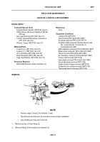
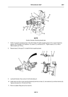
Perform steps (1) and (2) for Axle No. 3 only.
•
Tag and mark air lines prior to removal to ensure proper installation.
•
Cap and plug air lines upon removal.
1.
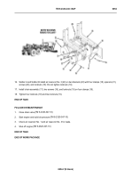
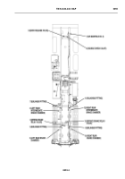
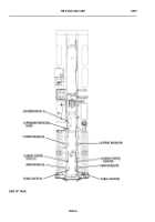
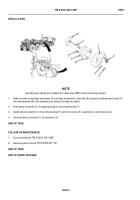
Remove air line (1) from fitting (2).
2.
Remove fitting (2) from lockout air chamber (3).
-
-
-
-
-
-
-
-
-
-
-
-
-
-
-
-
-
-
-
-
-
-
-
-
-
-
-
-
-
-
-
-
-
-
-
-
-
THAAD0108
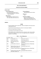
Tools and Special Tools
Forward Repair System (WP 0183, Item 6)
Lifting Device, Minimum Capacity 2,100 lbs
(953 kg)
Set, Cap and Plug (WP 0183, Item 17)
Tool Kit, General Mechanic’s: Automotive
(WP 0183, Item 25)
Wrench, Torque (WP 0183, Item 31)
Materials/Parts
Locknut, (2), (WP 0184, Item 70)
Locknut, (1), (WP 0184, Item 93)
Oil, Lubricating (WP 0186, Item 25)
Rust Preventive (WP 0186, Item 28)
Tags, Identification (WP 0186, Item 32)
Personnel Required
MOS 63B Wheeled vehicle mechanic (3)
References
None
Equipment Conditions
Unstow LHS (WP 0011)
Axle drained (TM 9-2320-325-14&P)
Air system drained (
Propeller shafts removed (transfer case to Axle
No. 3 and Axle No. 3 to Axle No. 4)
TM 9-2320-325-14&P
Slack adjusters removed (TM 9-2320-325-14&P)
Brake shoes removed (TM 9-2320-325-14&P)
Yokes removed (TM 9-2320-325-14&P)
Air chambers removed (TM 9-2320-325-14&P)
Torque rods removed (WP 0155)
Axle shafts removed (TM 9-2320-325-14&P)
Shock absorbers removed (WP 0152)
Height control linkage removed (WP 0150)
Suspension air springs removed (WP 0153)
Transverse beams removed (WP 0156)
TM 9-2320-347-10)
Back to Top

