TM-9-2320-440-13-P - Page 957 of 1616
TM 9-2320-440-13&P
0133-3
0133
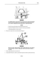
NOTE
•
Perform step (5) if lube fittings are damaged.
•
Note position of lube fittings prior to removal to ensure proper installation.
•
Position drain pan under hydraulic lines and fittings being removed.
•
Cap and plug all hydraulic lines upon removal.
5.
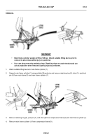
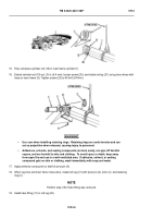
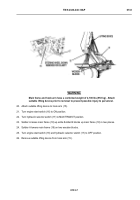
Remove two lube fittings (10 and 11) from main frame cylinder (1).
END OF TASK
INSTALLATION
-
-
-
-
-
-
-
-
-
-
-
-
-
-
-
-
-
-
-
-
-
-
-
-
-
-
-
-
-
-
-
-
- 5464654
1.
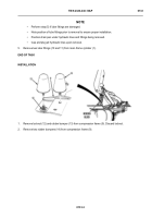
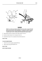
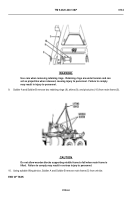
Remove locknut (12) and rubber bumper (13) from compression frame (9). Discard locknut.
2.
Remove two rubber bumpers (14) from compression frame (9).
Back to Top

