TM-9-2330-202-13-P - Page 360 of 552
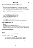
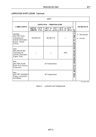
LUBRICATION CHART LEGEND - Continued
NOTE
Dotted leader lines indicate that lubrication is required on both sides of the equipment.
INTERVAL
S
A
MAN-HOURS*
* The man-hour time specified is the time you need to do all services prescribed for the particular interval.
2.7
1.0
OE/HDO • S
OE/HDO • S
OE/HDO • S
LUBRICANT • INTERVAL
LUBRICANT • INTERVAL
GAA • S
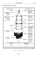
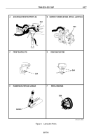
Master Cylinder
(M101A2, M101A3,
M116A2, and
M116A3)
(Notes 4 and View B)
(O)
Adjustable Front
Support Leg
(Note 3 and
View A) (O)
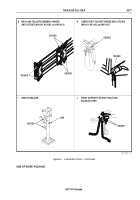
Rear Shackle Pins
(View D) (O)
Rear Stabilizer
(View I) (O)
Fixed Front Support
Leg Bolt and
Release Lever
(Note 2 and View J)
(O)
Handbrake Lever
and Linkage
(Notes 1 and 2 and
View E) (O)
Front Shackle Pin
(View C) (O)
Wheel Bearings
(Note 5 and View F)
(O)
Rack and Tailgate
Assembly Hinges
and Latches
(M101A1, M101A2,
and M101A3)
(Notes 1 and 2
and View G) (O)
Cargo Body
Tailgate Hinges
and Latches
(M101A1, M101A2,
and M101A3)
(Notes 1 and 2
and View H) (O)
Rear Stabilizer
(Notes 1 and 2
and View I) (O)
GAA • S
OE/HDO • S
OE/HDO • S
OE/HDO • S
GAA • S
GAA • S
GAA • S
OE/HDO • S
GAA • A
BFS • S
M116_M101_R052
Figure 1.
Lubrication Intervals.
TM 9-2330-202-13&P
0077
0077-4
Back to Top

