TM-9-2330-227-14-P - Page 190 of 576
TM 9-2330-227-14&P
HYDRAULIC TUBES AND FITTINGS - CONTINUED
ACTION
LOCATION
ITEM
REMARKS
INSTALLATION - CONTINUED
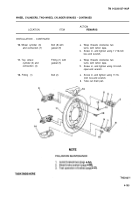
31.
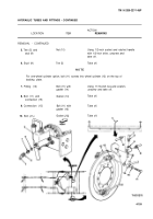
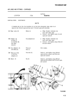
Connection (1)
Fitting (2) with
gasket (3)
32.
Fitting (2) and
Gasket (4)
connection (1)
33.
Left top wheel
Fitting (2) and
cylinder (5)
gasket (4)
34.
Nut (6)
Connection (7)
35.
Axle (8) and
Left tube (10)
two clamps (9)
36.
Bott (11)
Gasket (12)
37.
Connection (7)
Bolt (11) with
gasket (12)
38.
Bolt (11) and
Gasket (13)
connection (7)
Put in place.
Put in place.
Screw in, and tighten using 3/4-inch
box-end wrench.
Screw in, and tighten using 7/16-inch
open-end box and 9/16-inch
open-end wrenches.
Put in place.
Put in place.
Put in place.
Put in place.
NOT E
For the one-wheel cylinder option, bolt (11) screws into the wheel cylinder on the top of
the backing plate.
39.
Fitting (2)
Bolt (11) with
Screw in, and tighten using 11/16-inch
gasket (13)
box-end wrench.
40.
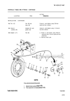
Stud (14)
Tee (15)
Put on.
41.
Tee (15) and
Nut (16)
Screw in, and tighten using 1/2-inch
stud (14)
socket and ratchet handle with 1/2-
inch drive.
42.
Tee (15)
Two nuts (17)
Screw in, and tighten using 7/16-inch
open-end box wrench.
43.
Axle (8) and
Two clamps (9)
Using ball-peen hammer, tap into place.
left tube (10)
4-112
Back to Top

