TM-9-2330-247-14-P - Page 102 of 320
TM 9-2330-247-14&P
Section Vlll. BRAKE SYSTEM MAINTENANCE
Page
Airbrake Chamber . . . . . . . . . . . . . . . . . . . .
4-79
Draincock . . . . . . . . . . . . . . . . . . . . . . . . . .
Air Couplings . . . . . . . . . . . . . . . . . . . . . . . .
4-88
Handbrake Cable and Lever Assembly . . .
Air Filters . . . . . . . . . . . . . . . . . . . . . . . . . . .
4-84
Hydraulic Tubes and Fittings . . . . . . . . . . .
Air Hoses and Fittings . . . . . . . . . . . . . . . .
4-89
Master Cylinder . . . . . . . . . . . . . . . . . . . . . .
Backing Plate . . . . . . . . . . . . . . . . . . . . . . .
4-63
Pressure Tank and Relay Valve . . . . . . . . .
Bleeding Brake System . . . . . . . . . . . . . . .
4-66
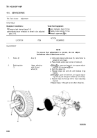
Service Brake . . . . . . . . . . . . . . . . . . . . . . .
Brakeshoe Assembly . . . . . . . . . . . . . . . . .
4-57
Wheel Cylinders . . . . . . . . . . . . . . . . . . . . .
4-30.
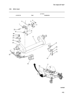
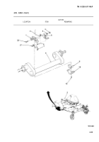
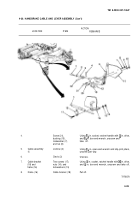
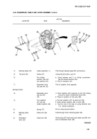
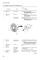
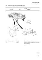
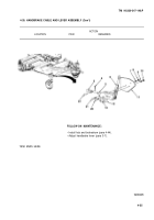
HANDBRAKE CABLE AND LEVER ASSEMBLY
Page
4-95
4-48
4-74
4-67
4-96
4-56
4-71
This Task Covers:
a.
Removal
b.
Installation
Initial Setup:
Equipment Conditions:
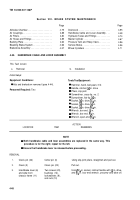
Tools/TestEquipment:
l Hub and brakedrum removed (para 4-44).
l Hammer, hand, ball-peen, 3 lb
Personnel Required:
Two
l Handle, ratchet,
~ in. drive
l Pilers, slip-joint
l Screwdriver, cross-tip, no. 2
l Screwdriver, flat-tip,
~ in.
l Socket, ~ in. drive, X6 in.
l Socket, ~ in. drive, ~ in.
l Socket, ~ in. drive, X6 in.
l Wrench, box-end, ~ in.
l Wrench, box-end, X6 in.
l Wrench, open-end, X6 in.
ACTION
LOCATION
ITEM
REMARKS
NOTE
l
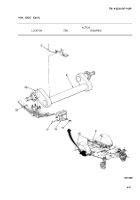
Both handbrake cable and lever assemblies are replaced in the same way. This
procedure is for the right; repeat for the left.
l
Ensure that handbrake lever is released before proceeding.
REMOVAL
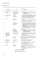
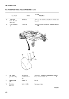
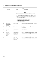
1.
Clevis pin (22)
Cotter pin (4)
Using slip-joint pilers, straighten and pull out.
2.
Clevis (3)
Clevis pin (22)
Pull out.
3.
Handbrake lever (6)
Two screws (20),
Using XG in. socket, ratchet handle with
x in. drive,
and side front
bushings (12),
and
~. in. box-end wrench, unscrew and take off.
chassis frame (11)
lockwashers (9),
and nuts (10)
4-48
Back to Top

