TM-9-2330-247-14-P - Page 108 of 320
TM 9-2330 -247-14&P
4-30.
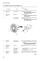
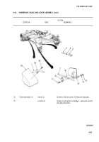
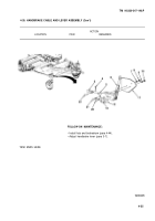
HANDBRAKE CABLE AND LEVER ASSEMBLY (Con’t)
ACTION
LOCATION
ITEM
REMARKS
NOTE
•
Ensure that handbrake lever is released before proceeding.
•
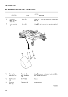
For trailers equipped with handbrake levers mounted on the
front corners of the trailer you must remove and discard the
following parts from the new handbrake lever before
proceeding with installation:
(a) Bellcrank pivot stud, nuts, and spacer.
(b) Bellcrank pin, washer, and cotter pin.
(c) Bellcrank and bushing.
32.
33.
34.
35.
36.
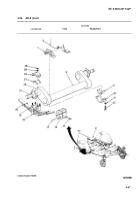
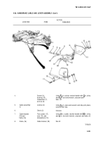
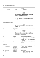
Clevis (3) and
handbrake lever
tongue (5)
Clevis pin (22)
Side front
chassis frame
(11)
Side front
chassis frame
(11) and
handbrake
lever (6)
Clevis pin (22)
Line up holes and push clevis pin (22) into place.
Cotter pin (4)
Slip into holes in clevis pin (22) and bend overusing
slip-joint pliers.
Handbrake lever
Place in position.
(6)
Two screws (20),
Screw in and tighten using
6 in. socket, ratchet
bushings (12),
handle with ½ in. drive, and XG in. box-end wrench.
Iockwashers (9),
and nuts (10)
Screw (21),
Screw in and tighten using %G in. socket, ratchet
bushing (13),
handle with ½ in. drive, and X6 in. box-end wrench.
Iockwasher (7),
and nut (8)
4-54
Back to Top

