TM-9-2330-330-14-P - Page 363 of 1116
TM 9-2330-330-14&P
0071 00-3
AIR BRAKE CHAMBERS MAINTENANCE—Continued 0071
00
INSTALLATION
NOTE
Apply thread sealing compound to threads of fittings.
1.
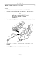
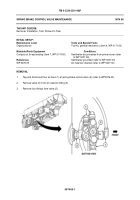
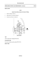
Install fittings on air brake chamber (8).
2.
Install air brake chamber (8) on bracket (9) with two nuts (5) and new lockwashers (6).
NOTE
Refer to WP 0069 00 for slack adjuster adjustment.
3.
Install jamnut (3) approximately 1-5/16 in. (3.33 cm) from end of push rod (4).
4.
Install yoke adapter (2) on push rod (4) approximately 3/8 in. (9.5 mm) from end of push rod (4).
5.
Turn manual adjustment hex (11) clockwise until yoke adapter (2) extends into the bore of yoke (1)
approximately 1/8 in. (3.2 mm). Thread adapter into yoke and tighten to 10 lb-ft (13.6 N•m).
6.
Tighten jamnut (3) to 34 to 50 lb-ft (46.0 to 67.8 N•m).
7.
Connect two brake hoses (7) to air brake chamber (8).
TEST
1.
Apply and hold a full-pressure brake application.
NOTE
Initial brake application will force out a small amount of
air. No air should be expelled from air chamber after initial
application. If air continues to be expelled from air chamber,
replace air chamber.
Back to Top

