TM-9-2330-342-10 - Page 104 of 500
Adjustment - Continued
4
5
1
2
3
4
Figure 4.
Drawbar Adjustment.
8.
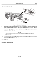
Align holes in tube assembly (Figure 4, Item 5) and drawbar structure (Figure 4, Item
4) and install locking pin (Figure 4, Item 1) into drawbar structure (Figure 4, Item 4).
9.
Close locking gate (Figure 4, Item 2) over locking pin (Figure 4, Item 1) on drawbar
structure (Figure 4, Item 4).
NOTE
Locking pin chain is used to keep locking gate in LOCKED position during
trailer operation.
10.
Position locking pin chain (Figure 4, Item 3) over locking gate (Figure 4, Item 2) and
around locking pin (Figure 4, Item 1).
END OF TASK
END OF WORK PACKAGE
TM 9-2330-342-10
0011
0011-4
Back to Top

