TM-9-2330-342-10 - Page 107 of 500
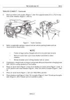
TRAILER CONNECT - Continued
5
6
7
8
9
1
12
13
14
11
11
10
4
15
1
10
4
3
2
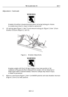
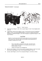
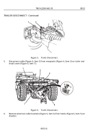
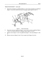
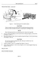
Figure 2.
Trailer Connect.
9.
Install cotter pin (Figure 2, Item 14) in coupler (Figure 2, Item 13) and slightly bend
cotter pin.
10.
If applicable, remove covers (Figure 2, Item 11) and connect service air gladhand
(Figure 2, Item 1) to service gladhand (Figure 2, Item 9) on vehicle and connect
emergency air gladhand (Figure 2, Item 4) to emergency air gladhand (Figure 2, Item
15) on vehicle.
CAUTION
Both the 12 volt (7-pin) and 24 volt (12-pin) cables must not be connected
at the same time. Only one cable can be hooked up during operation or
damage to equipment will result.
NOTE
•
The 12 volt cable is standard for this trailer. Use the 24 volt
system cable only when the 12 volt cable cannot be used or
blackout lights are used.
•
Cables are located in the stowage box.
11.
Remove cover (Figure 2, Item 2) from proper receptacle (Figure 2, Item 3) on trailer
and connect cable (Figure 2, Item 10) to receptacle (Figure 2, Item 3).
12.
Connect cable (Figure 2, Item 10) to receptacle (Figure 2, Item 8) on vehicle.
TM 9-2330-342-10
0012
0012-3
Back to Top

