TM-9-2330-342-10 - Page 451 of 500
REMOVAL - Continued
1
4
3
2
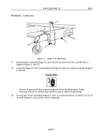
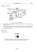
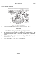
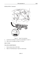
Figure 5.
Spare Tire Removal.
11.
Extend pulley assembly (Figure 5, Item 4) until second hole lines up with hole in
support (Figure 5, Item 2).
12.
Install pin (Figure 5, Item 1) and safety clip (Figure 5, Item 3) in pulley assembly (Figure
5, Item 4).
WARNING
Ensure all personnel wear protective gloves when handling cable. Cable
may fray. Failure to comply may result in injury or death to personnel.
13.
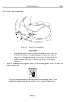
Turning winch bolt assembly (Figure 6, Item 1) counterclockwise, remove 10 ft (3 m)
of cable (Figure 6, Item 3) from winch assembly.
TM 9-2330-342-10
0055
0055-7
Back to Top

