TM-9-2330-342-23-P - Page 142 of 1348
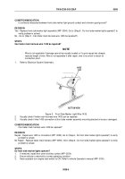
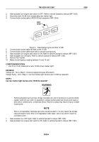
BLACK
RED
Figure 3.
Button Probe Leads.
4.
Connect button probe cable red and black leads together.
5.
Perform ICE Offset Test 91.
CONDITION/INDICATION
Does test equipment pass offset test?
DECISION
Yes - Go to (Step 4 - Is continuity measured between front side marker light ground contact and a known good
ground?).
No - Test equipment failed offset. Contact your Supervisor.
STEP 4
Is continuity measured between front side marker light ground contact and a known good ground?
1.
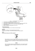
Remove two screws and lens cover (WP
0054).
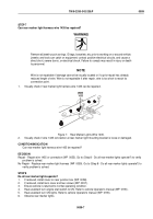
SCREWS
LENS
COVER
GROUND
CONTACT
Figure 4.
Front Side Marker Light Ground Contact.
2.
Connect button probe cable red lead to front side marker light ground contact.
3.
Connect button probe cable black lead to a known good ground.
4.
Perform ICE Test 91.
5.
Meter should display a reading less than 200 ohms.
TM 9-2330-342-23&P
0008
0008-4
Back to Top


