TM-9-2330-342-23-P - Page 769 of 1348
INSTALLATION - Continued
2
1
3
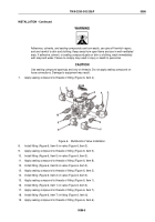
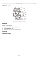
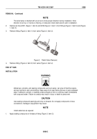
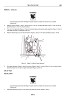
Figure 3.
Relief Valve Installation.
2.
Install fitting (Figure 3, Item 3) on valve (Figure 3, Item 2).
3.
Apply sealing compound on threads of fitting (Figure 3, Item 1).
4.
Install fitting (Figure 3, Item 1) on valve (Figure 3, Item 2).
NOTE
Refer to direction of arrow marking on valve to ensure proper installation.
5.
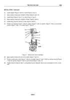
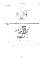
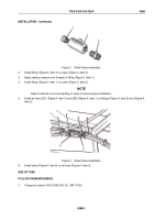
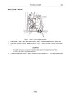
Install air lines 2231 (Figure 4, Item 3) and 2232 (Figure 4, Item 1) on fittings (Figure 4, Item 5) and (Figure 4,
Item 2).
1
2
3
4
5
6
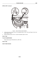
Figure 4.
Relief Valve Installation.
6.
Install valve (Figure 4, Item 6) on air lines (Figure 4, Item 4).
END OF TASK
FOLLOW-ON MAINTENANCE
1.
Charge air system (TM 9-2330-342-10). (WP
0190)
TM 9-2330-342-23&P
0088
0088-3
Back to Top

