TM-9-2330-356-14
SEMITRAILER, TANK: 5000 GALLON, BULK HAUL, SELF LOAD/UNLOAD M967 AND M967A1; SEMITRAILER, TANK: 5000 GALLON, FUEL DISPENSING, AUTOMOTIVE M969 AND M969A1; SEMITRAILER, TANK: 5000 GALLON, FUEL DISPENSING, UNDER/OVERWING AIRCRAFT M970 AND M970A1
TECHNICAL MANUAL; OPERATOR’S, UNIT, DIRECT SUPPORT, AND GENERAL SUPPORT MAINTENANCE MANUAL
OCTOBER 1990
TM-9-2330-356-14 - Page 172 of 528
TM 9-2330-356-14
Section VII. MAINTENANCE OF CHASSIS ELECTRICAL SYSTEM
4-12. Chassis Wiring
WARNING
When troubleshooting an electrical malfunc-
tion or performing electrical maintenance,
ALWAYS disconnect Intervehicular electrical
cable from semitrailer, and negative battery
cables at batteries. Failure to follow this warn-
ing may create a spark and explosion, result-
ing In serious injury or death to personnel.
a.
General.
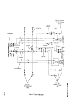
The chassis wiring of the semitrailer
consists of one wiring harness, seven electrical lead
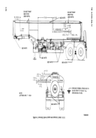
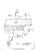
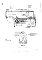
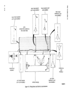
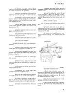
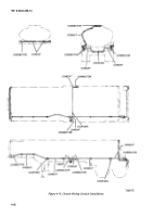
assemblies, and one receptacle assembly. Refer to figures
4-15 and 4-16 for schematic diagram and wire connections
of chassis electrical system. Wiring is as follows:
(1)
Receptacle Assembly. The
receptacle
(fig. 4-16) is mounted on the left front side of the
semitrailer. It connects the electrical system of the towing
vehicle with that of the semitrailer. The main wiring
harness of the semitrailer connects to the receptacle.
(2) Wiring
Harness.
This harness (fig. 4-16) runs
the entire length of the semitrailer through conduit, the
left rear composite light box, to the right rear composite
light box. It connects to various leads which in turn
connect to the lights on the semitrailer.
(3)
Rear Triple Marker Light Lead Assembly.
This
lead (fig. 4-16) is threaded from the triple marker box
through conduit to the left composite light box. There it
connects to one of six leads of the connector lead
assembly.
(4)
Right Front Marker Light Lead.
This lead
(fig. 4-16) is threaded from the right front marker box
through conduit to the left side of the semitrailer. There it
connects into the receptacle wiring, the wiring harness
and lead from the left front marker light.
(5)
Left Front Marker Light Lead Assembly.
This
lead (fig. 4-16) connects to the left front marker light and
to the right front marker light lead.
(6)
Right Side Marker Light Lead Assembly.
This
lead (fig. 4-16) is threaded from the right center marker
light box through conduit to the left center marker light
box. There it connects to the wiring harness and to the left
center marker light.
(7)
Right Rear Composite Light Lead Assembly.
This lead (fig. 4-16) is located in the right rear composite
composite light.
(8)
Left Rear Composite Light Lead Assembly.
This
lead (fig. 4-16) is located in the left rear composite light
box. It connects to the wiring harness in two places and to
the left composite light.
(9)
Connector Lead Assembly.
This lead
(fig. 4-16) is located in the left rear composite light box. It
is made up of six different leads, of which two connect to
left rear marker lights, two to the wiring harness, one to
triple marker light lead, and one to left composite light.
b.
Repair.
Most of the wiring can be repaired without
removing the harness and leads from the semitrailer.
(1) Clean end of harness leads with a damp cloth.
(2) Check ends of wire harness for frayed
insulation and broken wires. Tape or replace frayed wires.
(3) Inspect wires for bent, broken, or missing
terminals. Replace missing or damaged terminals.
c.
Replacement of Chassis Wiring.
(1)
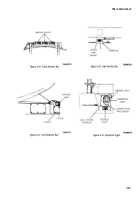
Composite Light and Connector Lead
Assemblies Replacement.
(a)
Remove six screws that secure
composite light box cover (fig. 4-23) to the light box.
Remove cover and gasket.
(b)
Start removing the old lead terminals
one connection at a time. As each lead terminal is
removed, connect the correct lead terminal of the
replacement lead before removing the next one. Continue
this process until the old lead is removed and the new one
is completely connected into the circuit.
(c)
Replace composite light cover and
gasket. Secure with six screws.
(d)
Test operation of lights.
(2)
Triple Marker Light Lead Assembly Replace-
ment.
(a)
Remove six screws that secure
composite light box cover (fig. 4-23) to the light box.
Remove cover and gasket.
(b)
In the composite light box, locate the
lead that comes from the triple marker box (fig. 4-20).
Disconnect this wire from the connector lead assembly
(fig. 4-16). Cut the terminal from the lead.
4-36
Back to Top

