TM-9-2350-238-20-2 - Page 339 of 495
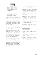
WARNING
TM 9-2350-238-20- 2
1
2
3
4
5
6
7
• Make sure MASTER switch i s
OFF before repairing electrica l
components. Failure to observ e
this warning could result in in-
jury to personnel .
• Failure to remove or disconnec t
the batteries before removing o r
installing any electrical wirin g
harness or lead may result in in-
jury or damaged equipment .
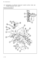
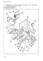
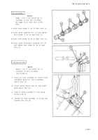
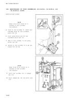
Disconnect and remove circuit breaker t o
floodlight switch electrical lead (1) fro m
15 amp circuit breaker (2) and 24 vol t
toggle switch (3) .
Disconnect and remove level wind switc h
to circuit breaker electrical lead assembly
(4) from 24 volt toggle switch (5) and 3 0
amp circuit breaker (6) .
Remove two machine screws (7), tw o
Iockwashers (8), level wind switch instruc -
tion plate (9), and toggle switch (5) fro m
angle bracket (10) .
Remove two machine screws (11), tw o
Iockwashers (12), and 24 volt flasher con-
trol toggle switch (13) from angle bracke t
(10) .
If damaged, remove two drive screws (14 )
and flasher signal switch identificatio n
plate (15) from angle bracket (10) .
Remove two machine screws (16), tw o
Iockwashers (17), floodlight switch iden -
tification plate (18), and toggle switc h
(19) from angle bracket (10) .
Remove four hexagon plain nuts (20), fou r
Iockwashers (21), four machine screw s
(22), and two 15 amp circuit breakers (2)
from angle bracket (10) .
8
9
1 0
1 1
1 2
1 3
Remove two hexagon plain nuts (23) ,
two Iockwashers (24), two machin e
screws (25), and 30 amp circuit breake r
(6) from angle bracket (10) .
Remove flasher indicator assembly ligh t
lens (26) and flasher indicator lens pre-
formed packing (27) from flasher indi -
cator light (28) .
Remove LED (29) from flasher indicator
housing (30) .
Remove two machine screws (31), tw o
Iockwashers (32), and flasher indicato r
housing (30) from angle bracket (10) .
Remove two machine screws (33), tw o
Iockwashers (34), utility outlet cove r
(35), and utility outlet electrical lead (36)
from angle bracket (10) .
Remove two hexagon plain nuts (37) ,
two Iockwashers (38), two hexago n
capscrews (39), and cab signal ligh t
thermal flasher (40) from angle bracke t
(10) .
INSPECTION/REPAI R
1
2
3
Check for broken, damaged, or missin g
parts .
If angle bracket is broken, damaged, or
missing, repair is by replacement of nex t
higher assembly .
Repair is by replacement of authorize d
parts (TM 9-2350-238-24P-2) which d o
not meet inspection criteria .
2-29 9
Back to Top

