TM-9-2350-238-20-2 - Page 341 of 495
WARNING
TM 9-2350-238-20- 2
1
2
3
4
5
6
7
8
9
1 0
1 1
1 2
1 3
1 4
Failure to remove or disconnect the batteries before removing or installing any
electrical wiring harness or lead may result in injury or damaged equipment .
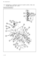
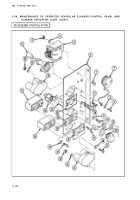
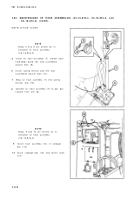
Install two hexagon capscrews (1), cab signal light flasher (2), two new Iockwashers (3) ,
and two hexagon plain nuts (4) on angle bracket (5) .
Install utility outlet electrical lead (6), utility outlet cover (7), two new Iockwashers (8), an d
two machine screws (9) on angle bracket (5) .
Install flasher indicator housing (10), two new Iockwashers (11), and two machine screw s
(12) on angle bracket (5) .
Instal l
Instal l
Instal l
Instal l
LED (13) in flasher indicator housing (10) .
new preformed packing (14) on flasher indicator light (15) .
flasher indicator assembly light lens (16) in flasher indicator light housing (10) .
two machine screws (17), 30 amp circuit breaker (18), two new Iockwashers (19) ,
and two hexagon plain nuts (20) on angle bracket (5) .
Install four machine screws (21), two 15 amp circuit breakers (22), four new Iockwasher s
(23), and four hexagon plain nuts (24) on angle bracket (5) .
Install 24 volt toggle switch (25), floodlight switch identification plate (26), two ne w
Iockwashers (27), and two machine screws (28) on angle bracket (5) .
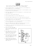
If removed, install flasher signal switch identification plate (29) and two new drive screws
(30) on angle bracket (5).
Install 24 volt flasher signal toggl e
switch (31), two new Iockwashers (32) ,
and two machine screws (33) on angl e
bracket (5) .
Install toggle switch (34), level win d
switch instruction plate (35), two ne w
Iockwashers (36), and two machin e
screws (37) on angle bracket (5) .
Install and connect level wind switch t o
circuit breaker electrical lead assembly
(38) to 24 volt toggle switch (25) an d
30 amp circuit breaker (18) .
Install and connect circuit breaker t o
floodlight switch electrical lead (39) t o
15 amp circuit breaker (40) and 24 vol t
toggle switch (41) .
2-30 1
Back to Top


