TM-9-2350-238-34-1 - Page 193 of 292
TM 9-2350-238-34-1
7
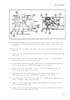
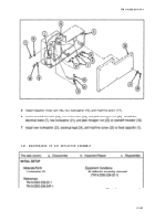
Connect lead from electrical indicator lead assembly terminal 3, lead (27) from electrical lea d
assembly pin D, and one end of lead (28) to circuit breaker terminal 17. Secure three leads
with screw .
8
Connect lead (29) from indicator lamp terminal 2 to terminal 19 of RUN/OFF/START toggl e
switch (20) .
9
1 0
1 1
1 2
1 3
1 4
1 5
1 6
Connect lead (30) from electrical lead assembly pin E to terminal 19 of RUN/OFF/START toggle
switch (20) .
Connect electrical lead (31) from HI/LO toggle switch (24) terminal 13 to RUN/OFF/START
toggle switch terminal 20. Secure leads with screw .
Connect lead (32) from electrical lead assembly terminal C to RUN/OFF/START toggle switc h
(20) terminal 20. Secure to RUN/OFF/START toggle switch with screw .
Connect lead (33) from circuit breaker terminal 17 to RUN/OFF/START toggle switch (20)
terminal 15. Secure to toggle switch with screw.
Install heater control switch electrical lead (34) from electrical lead assembly pin A, with
retaining plate (35), and screw to RUN/OFF/START toggle switch (20) terminal 14.
Install retaining plate (35) and one end of jumper (36) to RUN/OFF/START toggle switch (20)
terminal 21. Secure to toggle switch with screw.
Connect other end of jumper (36) to RUN/OFF/START toggle switch (20) terminal 18, and
secure to toggle switch with screw.
Connect lead (37) from electrical lead assembly pin B to Hi/LO toggle switch (24) terminal 12.
Secure lead to HI/LO toggle switch with screw.
2-181
Back to Top


