TM-9-2350-256-10 - Page 148 of 796
INSTALLATION
1.
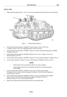
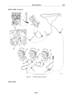
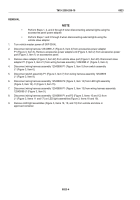
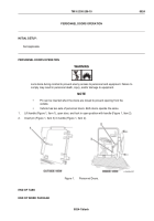
Position light assemblies (Figure 1, Item 1) so as to provide additional illumination when performing tasks.
Figure 1.
External Lights Placement.
2.
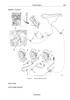
Connect wiring harness assembly 12543899 P1 and P2 (Figure 2, Items 10 and 12) to
J1 (Figure 2, Items 11 and 17) on LED lights (Figure 2, Items 18 and 19).
3.
Connect wiring harness assembly 12543899 J1 (Figure 2, Item 9) to wiring harness assembly 12543899
P1 (Figure 2, Item 13).
4.
Connect wiring harness assembly 12543899 P2 (Figure 2, Item 14) to J1 (Figure 2, Item 15) on
LED light (Figure 2, Item 16).
5.
Connect wiring harness assembly 12543899 J1 (Figure 2, Item 8) to switch assembly P1 (Figure 2, Item 7).
6.
Connect switch assembly J1 (Figure 2, Item 6) to wiring harness 12543898 P1 (Figure 2, Item 5).
NOTE
•
Perform Step 7 when connecting the light kit to the slave receptacle.
•
Perform Steps 8 and 9 when connecting to the light kit to the accessories panel
power adapter.
7.
Connect wiring harness assembly 12543898 J1 (Fig 2, Item 4) to slave power adapter
P1 (Figure 2, Item 21), and connect slave adapter end (Figure 2, Item 22) to slave receptacle on
vehicle (Figure 2, Item 20).
8.
Connect wiring harness assembly 12543898 J1 (Figure 2, Item 4) to accessories power adapter
(Figure 2, Item 3), and connect accessories power adapter end (Figure 2, Item 2) to
power port (Figure 2, Item 1) on the accessories panel.
9.
Apply vehicle master power (WP 0004) before turning on the external lights.
TM 9-2350-256-10
0023
0023-2
Back to Top

