TM-9-2350-256-10 - Page 145 of 796
LIGHT SWITCH ASSEMBLY OPERATION
INITIAL SETUP:
Equipment Condition
MASTER switch in ON position (WP 0004)
LIGHT SWITCH ASSEMBLY OPERATION
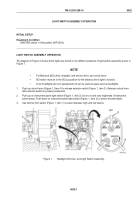
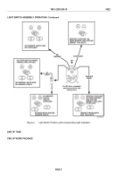
The diagram in Figure 2 shows which lights are turned on by different positions of light switch assembly shown in
Figure 1.
NOTE
•
For Blackout (BO) drive, stoplight, and service drive, use unlock lever.
•
BO switch must be in the BO up position for the blackout drive light to function.
•
Inner headlights are non-operational but can be used as spare service headlights.
1.
Push up unlock lever (Figure 1, Item 4) to release selector switch (Figure 1, Item 3). Release unlock lever
after selector switch is properly positioned.
2.
Push up on instrument panel light switch (Figure 1, Item 2) to turn on and vary brightness of instrument
panel lamps. Push down on instrument panel light switch (Figure 1, Item 2) to select the park lights.
3.
Use dimmer foot switch (Figure 1, Item 1) to select between high and low beams.
Figure 1.
Headlight, Dimmer, and Light Switch Assembly.
TM 9-2350-256-10
0022
0022-1
Back to Top

