TM-9-2350-260-20-1-3 - Page 68 of 783
TM 9-2350-260-20-1-3
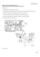
MASTER CONTROL PANEL ASSEMBLY RELACEMENT (Sheet 4 of 5)
INSTALLATION:
1.
Position master control panel (A) into tank.
2.
Support master control panel (A) face side down with connector to the right and away from you.
NOTE
Apply silicone compound (Item 32, Appendix D) to all male connectors prior to
installation.
NOTE
If circuit 25 was disconnected, reconnect
3.
Connect circuit lead no. 415 connector (B) to indicator light (C).
4.
Connect circuit lead no. 415 connector (D) to switch (E).
5.
Using spanner wrench, connect main light switch connector (F) to switch (G).
6.
Connect circuit lead no. 15 connectors (H).
7.
Connect circuit lead no. 19 connector (J) to switch (K).
Go on to Sheet 5
10-56
Back to Top


