TM-9-2350-261-20-1 - Page 82 of 346
TM 9-2350-261-20-1
THEORY OF OPERATION — Continued
0003 00
DIFFERENTIAL COMPONENTS
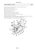
The differential consists of three major assemblies. These are the right angle gearbox (1), steering unit with brake shoes (2),
and two output shafts (3).
Power flow is from the transmission to the right angle gearbox (1) to the steering unit (2).
When driving straight forward, the steering unit (2) delivers equal power to both output shafts (3). Pressure on either steering
lever slows or stops the right or left brake drum, inside the center steering unit (2), and reduces the speed of the right or left
output shaft (3). By slowing down one side you increase the speed of the other, and the carrier will turn in the direction
of the applied brake.
Equal pressure on both steering levers applies both brakes and slows or stops the carrier.
The differential overheat switch (4) is connected to a warning light in driver’s compartment. When warning light comes on, it
means oil temperature is too high.
000300-7
Back to Top


