TM-9-2350-261-34 - Page 355 of 785
TM 9-2350-261-34
REPLACE SERRATED LOCK RING SCREW INSERTS — Continued
0050 00
3.
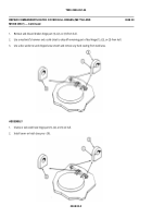
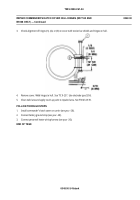
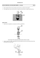
Drive in extractor tool (3) to screw out insert (4). As insert comes out, it will push out lock ring (5).
4.
If lock ring (5) does not come out with insert (4), hit ring with a punch and hammer to collapse ring. Remove ring.
INSTALLATION
1.
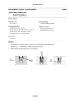
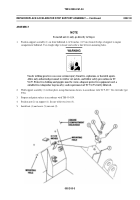
Install insert (1) in threaded hole. Use inserter (2). See Table 1, page 0050 00-3.
NOTE
Do not attempt to drive lock ring beyond the top surface of insert serrations.
2.
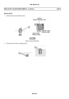
Using lock ring drive tool (Table 1, page 0050 00-3), drive lock ring (3) into surface until drive tool (4) touches surface.
Lock ring will be set at proper depth.
0050 00-2
Back to Top


