TM-9-2350-277-20-3 - Page 160 of 941
TM 9-2350-277-20-3
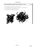
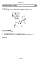
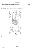
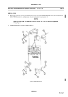
REPLACE INSTRUMENT PANEL ON-OFF SWITCHES
0282 00
THIS WORK PACKAGE COVERS:
Removal (page 0282 00-1).
Installation (page 0282 00-3).
INITIAL SETUP:
Maintenance Level
Unit
Tools and Special Tools
General Mechanic’s Tool Kit (WP 0926 00, Item 65)
Materials/Parts
Lockwasher (10)
Personnel Required
Mechanic
References
TM 9-2350-277-10
Equipment Condition
Engine stopped (TM 9-2350-277-10)
Carrier blocked (TM 9-2350-277-10)
Battery ground strap disconnected (WP 0337 00 or
WP 0338 00)
REMOVAL
NOTE
There are four or five toggle switches on the instrument panel. Replace all toggle switches
the same way, except for number of circuit leads, and guard on DNV-POWER switch (old
configuration) or DVE-POWER switch (new configuration).
NOTE
Do not disconnect more than one switch at a time. Mark each circuit lead to make sure you
reconnect to correct contacts. See applicable wiring diagram at end of this manual.
028200-1
Change 5
Back to Top


