TM-9-2350-277-20-3 - Page 294 of 941
TM 9-2350-277-20-3
REPLACE VARIABLE SPEED FAN DRIVE SENSORS AND
SWITCHES (NEW CONFIGURATION)
0321 01
THIS WORK PACKAGE COVERS:
Removal (page 0321 01-1).
Installation (page 0321 01-2).
INITIAL SETUP:
Maintenance Level
Unit
Tools and Special Tools
General Mechanic’s Tool Kit (WP 0926 00, Item 65)
Materials/Parts
Tie straps
Personnel Required
Unit Mechanic
Equipment Condition
Engine stopped (see your -10)
Carrier blocked (see your -10)
Pow er plant rear access panel rem oved ( see y our -10)
Driver’s power plant access panel removed
(see y our -10 )
Battery ground strap disconnected (WP 0337 00),
(WP 033 8 00), or (WP 033 9 00)
REMOVAL
NOTE
Install covers on disconnected electrical component cable connections during maintenance.
Use any appropriate material to prevent damage to components. Mark and tag all connections
prior to disconnection.
1.
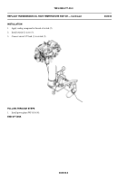
Disconnect variable speed wiring harness plug P3 (1) from engine running switch S2 (2).
2.
Remove engine running switch S2 (2) from tee (3) on secondary fuel filter (4).
3.
Disconnect variable speed wiring harness plug P6 (5) from engine coolant sensor 3A3 (6). Remove engine coolant
sensor 3A3 (6).
032101-1
Change 4
Back to Top

