TM-9-2350-277-20-5 - Page 38 of 1047
TM 9-2350-277-20-5
REPLACE FRONT BILGE PUMP PIPES — Continued
0631 00
INSTALLATION
NOTE
1.
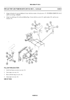
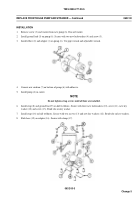
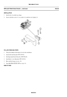
Remove backing from new gasket (1). Install gasket, sticky side down, and sight glass (2) on upper pipe (3). Secure with
two U-bolts (4), four washers (5), and new locknuts (6). Tighten nuts until gasket is compressed.
2.
Install new grommet (7) in driver’s compartment bulkhead.
3.
Install clamp (8) and hose (9) on upper pipe (3). Secure hose to pipe with clamp (10).
4.
Slide pipe (3) through grommet (7) and install hose (9) on discharge outlet. Secure with clamp (11).
5.
Install clamp (12) and two hoses (13) and (14) on lower pipe (15). Secure hoses to pipe with two clamps (16).
6.
Install hose (14) on bilge pump (17). Secure with clamp (18).
7.
Install hose (13) on upper pipe (3). Secure with clamp (19).
8.
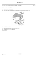
Align two clamps (8) and (12) with two bulkhead weldnuts. Secure with two new lockwashers (20) and screws (21).
FOLLOW-THROUGH STEPS
1.
Install front bilge pump strainer (WP 0632 00).
2.
Turn MASTER SWITCH to ON. See TM 9-2350-277-10. Operate bilge pump and check for leaks. Turn all switches
OFF.
3.
Install hull front access cover (WP 0449 00).
4.
Close power plant access door. See TM 9-2350-277-10.
END OF TASK
0631 00-3/4 blank
Change 5
Do not overtighten nuts. Sight glass will break.
Back to Top

