TM-9-2350-311-10 - Page 442 of 775
TM 9-2350-311-10
3-6
ARMAMENT AND CAB MAINTENANCE — CONTINUED
3-6.3
Rammer Assembly
a. Adjustment
Do not spot paint bridge clamp or plunger as it could cause damage to equipment. Lubricate
rammer blocking valve plunger and roller (item 13, Appx G).
1
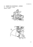
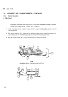
If tray (1) contacts rammer mounting bracket (2) refer to steps 2 and 3 to adjust position of rammer
mounting bracket.
2
With rammer assembly (3) in stowed position, adjust two cap screws (4) to provide a clearance of
approximately 1/4 inch (6.4 mm) between tray (1) and rammer mounting bracket (2).
3
Securely lock cap screws (4) in position with two hex nuts (5) and Iockwire (6).
NOTE
RAMMER ASSEMBLY IS SHOWN IN RAM POSITION.
3-42
Back to Top


