TM-9-2350-311-10 - Page 440 of 775
TM 9--2350--311--10
3--40
Change 2
3--6
ARMAMENT AND CAB MAINTENANCE — CONTINUED
3--6.1
Maintenance of Sighting and Fire Control Equipment — Continued
f.
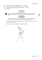
Cleaning Glass on Fire Control Equipment
Using lint-free cloth (item 10, Appx D) and optical lens cleaning compound (item 9, Appx D), clean glass on eyepieces
and counter windows on all fire control equipment. Clean glass on panoramic telescope ballistic cover.
3--6.2
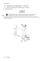
Cannon Equilibrator
Adjustment
CAUTION
With the MASTER switch and CAB POWER switch to ON, the equilibrator valve open (turned
left), and the system drain valve open, the complete power pack assembly will be pumped dry.
Equilibrating hydraulic fluid comes from the power pack assembly. To prevent damage to
equipment, do not operate the system with low fluid levels.
NOTE
Variations in temperatures can affect elevating or depressing of the cannon tube. The cannon
equilibrator, which counterbalances the weight of the cannon tube, must be adjusted if more
effort is required to elevate than depress or vice-versa.
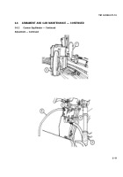
1
Using M1A1 gunner’s quadrant or M15 elevation quadrant, set cannon tube elevation at + 266 mils.
2
Using the elevating hand pump (1), elevate and depress the cannon tube to determine if it is as easy to
elevate as it is to depress.
3
If no difference is detected, no adjustment is required.
NOTE
If possible use two personnel to perform task in step 4 to reduce time required.
4
If cannon tube is harder to elevate than depress, use equilibrator hand pump (2) and assistant gunner’s
control handle (3) simultaneously to get cannon to maximum elevation. With cannon at maximum
elevation and CAB POWER switch to ON, open equilibrator valve (white knob) (4) to allow system to
equalize (approximately 15 seconds). Close equilibrator valve (white knob) and repeat steps 1, 2, and 3.
5
If cannon tube is harder to depress than elevate, slowly open system drain valve (red knob) (5). Place a
clean container under drain tube (6) and bleed off a small quantity of hydraulic fluid.
6
Repeat step 2 and adjust system with steps 4 or 5 until no difference is detected.
Back to Top

