TM-9-2350-311-10 - Page 516 of 775
TM 9-2350-311-10
3-7
3-7.12
11
12
13
14
15
16
17
18
19
20
21
FIRE CONTROL ALINEMENT TESTS AND MEASUREMENTS — CONTINUED
Testing the M15 Elevation Quadrant and Auxiliary Quadrant (On M145/M145A1 Telescope Mount)
— Continued
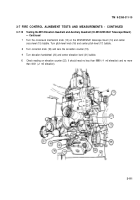
Zero correction counters (5) and elevation counter (8) on the M15 elevation quadrant (2) and center the
cross-level (3) bubble.
Using the M15 elevation quadrant (2), elevate or depress the cannon tube to zero mils elevation.
Set the M1A1 gunner’s quadrant (9) on M15 elevation quadrant (2) seats (10). Turn micrometer knob
(11) and center bubble (12). Record the value on the M1A1 gunner’s quadrant.
Turn correction knob (18) on the M145/M145A1 telescope mount (14) to place a + 5 mil reading on the
correction counter (19). Check the reading on the elevation counter (22). It should have changed by 5
mils. If it doesn’t, notify unit maintenance.
Turn the elevation handwheel (20) on the M145/M145A1 telescope mount (14) until elevation counter
(22) reads 0.
Elevate or depress cannon tube until elevation level (21) bubble centers.
Place + 5 mil and value recorded in step 13 on the M1A1 gunner’s quadrant (9). Set the M1A1 gunner’s
quadrant back on the M15 elevation quadrant (2). The M1A1 gunner’s quadrant bubble (12) should
center. If it does not, notify unit maintenance.
Now, zero all counters. Repeat steps 12 through 17, only this time, use a value of – 5 mils. If the M1A1
gunner’s quadrant (9) bubble (12) does not center, the correction counters (5) are inaccurate. Notify unit
maintenance.
Remove the – 5 mils from the M1A1 gunner’s quadrant (9).
Using the M15 elevation quadrant (2), zero the cannon tube.
Set the M1A1 gunner’s quadrant (9) on the M15 elevation quadrant (2) seats (10). Level the bubble (12)
on the M1A1 gunner’s quadrant using the micrometer knob (11), then record the value on the M1A1
gunner’s quadrant.
3-112
Back to Top

