TM-9-2350-311-10 - Page 511 of 775
TM 9-2350-311-10
3-7 FIRE CONTROL ALINEMENT TESTS AND MEASUREMENTS —
CONTINUED
3-7.10
1
2
3
4
5
6
Scribe Verification Using the M145/M145A1 Telescope Mount Check
With the howitzer still on the jacks, place the cannon tube at zero elevation. Be sure the M15 elevation
quadrant scribe lines are still matched (para 3-7.8).
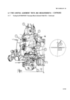
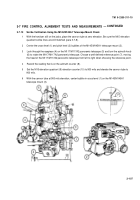
Center the cross-level (1) and pitch level (2) bubbles of the M145/M145A1 telescope mount (3).
Look through the eyepiece (4) on the M117/M117A2 panoramic telescope (5) and turn the azimuth knob
(6) to rotate the M117/M117A2 panoramic telescope. Choose a well-defined reference point (7), moving
the head of the M117/M117A2 panoramic telescope from left to right when choosing the reference point.
Record the reading that is on the azimuth counter (8).
Set the M15 elevation quadrant (9) elevation counter (10) to 900 mils and elevate the cannon tube to
900 mils.
With the cannon tube at 900 mils elevation, center bubble in cross-level (1) on the M145/M145A1
telescope mount (3).
3-107
Back to Top


