TM-9-2350-311-10 - Page 517 of 775
TM 9-2350-311-10
3-7 FIRE CONTROL ALINEMENT TESTS AND MEASUREMENT - CONTINUED
3-7.12 Testing the M15 Elevation Quadrant and Auxiliary Quadrant (On M145/M145A1 Telescope Mount)
— Continued
NOTE
When checking the M15 elevation quadrant at 400 and 800 mils elevation (as in step 22), also
check the M145/M145A1 telescope mount elevation counter. It should read 400 mils and 800 ± 1
mil at those elevations.
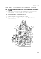
22
Using the M15 elevation quadrant (2), elevate the cannon tube from 0 mils to 400 mils and then to 800
mils, At each elevation, place the elevation counter (8) reading (400, then 800) plus the value recorded
in step 21 on the M1A1 gunner’s quadrant (9) and set the M1A1 gunner’s quadrant on the M15 elevation
quadrant (2) seats (10).
Example:
Elevations placed on elevation counter
400.0
800.0
Value measured in step 21 at zero elevation
+0.7
+ 0.7
Values placed on gunner’s quadrant
400.7
800.7
The bubble (12) in the M1A1 gunner’s quadrant (9) should center. If the bubble centers, the test is complete. If the
bubble doesn’t center, center it by turning the micrometer knob (11). After centering the M1A1 gunner’s quadrant, read
the value now on the elevation counter (8). It should not have changed more than ± 0.5 mils from the original reading. If it
does, the M15 elevation quadrant (2) is in error and must be turned into unit maintenance.
3-113/(3-114 blank)
Back to Top

