TM-9-2350-311-20-1 - Page 373 of 1275
TM 9-2350-311-20-1
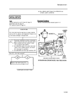
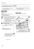
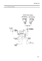
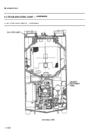
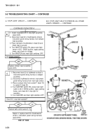
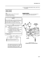
(1) ONE OR MORE INSTRUMENT PANEL LIGHTS FAIL
TO OPERATE
INITIAL SETUP
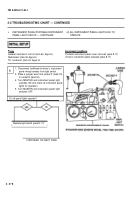
Tools
. .
General mechanic’s tool kit (item 64, Appx H)
Portable instrument panel cover removed (para 8-17)
Multimeters (item 36, Appx H)
Driver’s instrument panel released (para 8-17)
TA-1 probe kit (item 43, Appx H)
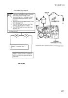
Before troubleshooting instrument panel lights, be sure
that service drive lights are operational. The following
procedure applies to both portable and driver’s
instrument panels and accessory control box lights.
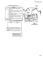
m
A
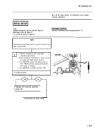
1. Remove inoperative panel light bulb
(para 8-17).
2. Place red lead of multimeters in center contact
of socket and black lead to ground.
3. Turn MASTER switch ON, instrument panel
light switch on, and check for voltage.
4. Turn MASTER and instrument panel light
switches OFF.
Is voltage present?
I
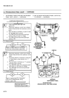
Replace panel light bulb (para 8-1 7).
For portable instrument panel, go to step B.
For driver’s instrument panel, go to step F.
For accessory control box, go to step D.
3-273
NOTE
Back to Top

