TM-9-2350-311-20-1 - Page 376 of 1275
TM 9-2350-311-20-1
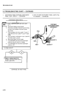
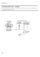
3-3 TROUBLESHOOTING CHART — CONTINUED
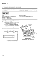
x.
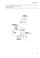
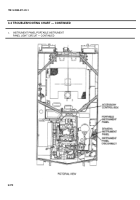
INSTRUMENT PANEL/PORTABLE INSTRUMENT
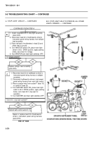
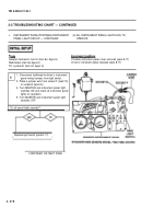
(1) ONE OR MORE INSTRUMENT PANEL LIGHTS FAIL
PANEL LIGHT CIRCUIT — CONTINUED
TO OPERATE — CONTINUED
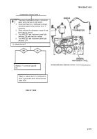
CONTINUED FROM STEP A
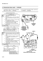
1.
2.
3.
4.
5.
Install inoperative panel light bulb
(para 8-17).
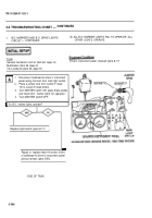
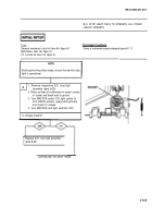
Disconnect accessory control box-to-heater/
blower wiring harness from accessory control
panel.
Place red lead of multimeters in socket D (lead
40) and black lead to ground.
Turn MASTER and instrument panel light
switches ON and check for voltage.
Turn MASTER and instrument panel light
switches OFF.
Is voltage present?
Repair or replace lead 40 of accessory
control box wiring harness (para 8-53).
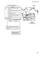
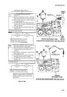
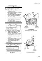
1.
2.
3.
4.
5.
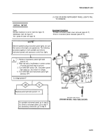
Reconnect accessory control box-to-heater
blower wiring harness from accessory control
panel.
Disconnect lead 40 of accessory control box
to heater/blower wiring harness from “Y”
connector.
Place red lead of multimeters on “Y” connector
and black lead to ground.
Turn MASTER switch ON, instrument panel
light switch on, and check for voltage.
Turn MASTER and instrument panel light
switches OFF.
Is voltage present?
Repair or replace lead 40 of accessory
control box-to-heater/blower wrong
harness (para 8-2).
3-276
Back to Top

