TM-9-2350-311-20-1 - Page 384 of 1275
TM 9-2350-311 -20-1
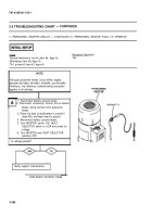
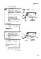
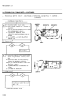
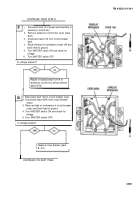
3-3 TROUBLESHOOTING CHART —
CONTINUED
z.
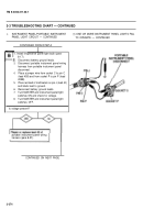
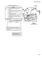
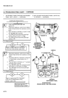
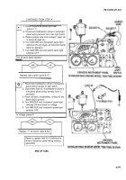
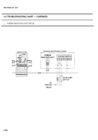
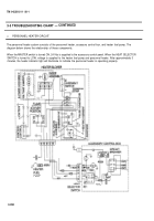
PERSONNEL HEATER CIRCUIT
The personnel heater system consists of the personnel heater, accessory control box, and heater fuel pump. The
diagram below shows the relationship of these components.
When the MASTER switch is turned ON, 24 Vdc is supplied to the accessory control panel. When the HEAT SELECTOR
SWITCH is turned to LOW, voltage is supplied to the heater fuel pump and personnel heater. After approximately 3
minutes, the heater indicator light will illuminate to indicate the personnel heater is operating properly.
3-284
Back to Top

