TM-9-2350-311-20-1 - Page 389 of 1275
TM 9-2350-311-20-1
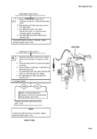
CONTINUED FROM STEP E
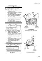
1.
2.
3.
4.
5.
6.
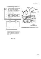
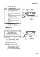
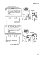
Reconnect lead 10 of power lead assembly to
accessory control box.
Remove accessory control box cover (para
8-20).
Disconnect lead 10A from circuit breaker
input.
Place red lead of multimeters in lead 10A and
black lead to ground.
Turn MASTER switch ON and check for
voltage.
Turn MASTER switch OFF.
I
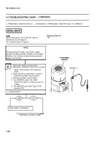
Is voltage present?
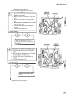
Repair or replace lead 10/10A of
accessory control box wiring harness
(para 8-53).
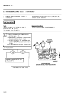
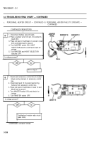
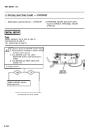
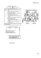
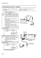
1. Reconnect lead 10A to circuit breaker input.
2. Disconnect lead 400A from circuit breaker
output.
3. Place red lead of multimeters in circuit breaker
output and black lead to ground.
4. Turn MASTER switch ON and check for
voltage.
5. Turn MASTER switch OFF.
I
Is voltage present?
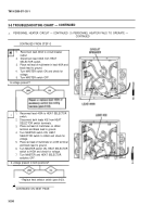
Replace circuit breaker (para
CONTINUED ON NEXT PAGE
3-289
8-20) .
Back to Top

