TM-9-2350-311-20-1 - Page 429 of 1275
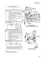
CONTINUED FROM STEP B
1
E
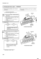
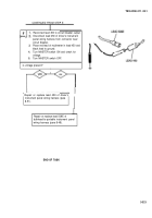
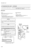
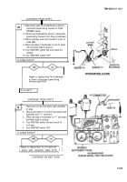
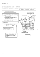
1. Reconnect lead 76B to bulkhead-to-portable
instrument panel wiring harness.
2. Leave in-tank fuel pump lead assembly
disconnected from relay.
3. Place red lead of multimeter in socket A (lead
10) and black lead to ground.
4. Turn MASTER switch ON and check for
voltage.
5. Place red lead of multimeter in socket B (lead
10) and black lead to ground.
6. Turn MASTER switch ON and check for
voltage.
7. Turn MASTER switch OFF.
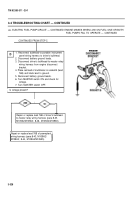
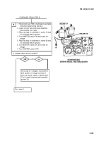
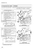
Is voltage present at both sockets?
I
I
Go to step K, if voltage is not present in
both sockets. If voltage is present in
only one socket, repair or replace lead
10 of in-tank fuel pump lead assembly
(para 8-73).
TM 9-2350-311-20-1
Go to step N.
3-329
Back to Top

