TM-9-2350-311-20-1 - Page 59 of 1275
TM 9-2350-311-20-1
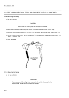
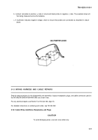
b. Connect red probe to positive (+) side of circuit and black probe to negative (-) side. The example shows 24
Vdc being measured across the batteries.
c. If multimeter indicates negative voltage, check to ensure that probes are connected as described in step b
above.
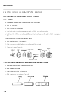
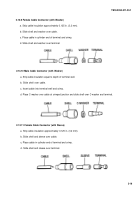
2-13 WIRING HARNESS AND CABLE REPAIRS
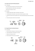
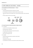
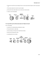
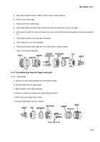
Step-by-step procedures for the disassembly and assembly of typical receptacles, plugs, and cable connectors used on
the M109A2/M109A3/M109A4/M109A5 are shown here.
For any electrical repairs use Electric Tool Kit (item 63, Appx H).
For detailed instructions on soldering and solder, see TB SIG 222.
2-13.1 Cable Wires, Identifiers, Receptacles, and Plugs
To avoid damaging wires, use resin core solder only.
2-11
CAUTION
Back to Top

