TM-9-2350-311-20-1 - Page 63 of 1275
TM 9-2350-311-20-1
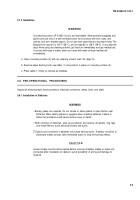
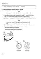
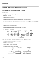
e. Push insert into shell from rear until seated. Groove in insert must be alined with guide in shell to ensure proper
fit.
f. Push socket contacts into insert from rear until seated.
g. Push grommet down cable leads and over solder wells of socket contacts.
h. Screw nut onto shell assembly.
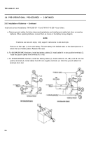
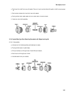
2-13.5 Typical Male-Type Panel Mounting Receptacle with Ridged Locking Nut
2-13.5.1 Disassembly
a. Unscrew nut from shell assembly and slide back on cable.
b. Push grommet back on cable leads.
c. Drive pin contacts out through rear of insert with pin extractor.
d. Push insert out through rear of shell.
e. Unsolder leads from pin contacts.
2-15
Back to Top

