TM-9-2350-311-20-1 - Page 830 of 1275
TM9-2350-311-20-1
a.
b.
Removal
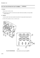
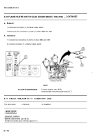
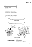
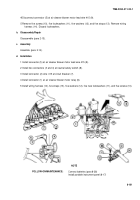
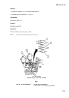
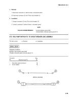
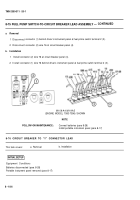
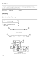
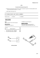
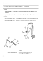
1 Disconnect connector (1) behind driver’s instrument panel.
2 Disconnect connector (2) wire 76 at circuit breaker (3).
Installation
1 Connect connector (2) wire 76 at circuit breaker (3).
2 Connect connector(1) behind driver’s instrument panel.
NOTE
FOLLOW-ON MAINTENANCE:
Connect batteries (para 8-28)
Install portable instrument panel (para 8-17)
8-75
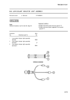
FUEL PUMP SWITHCH-TO -TO CIRCUIT BREAKER LEAD ASSEMBLY
This task covers:
a. Removal
b. Installation
Batteries disconnected (para 8-28)
Portable instrument panel removed (para 8-17)
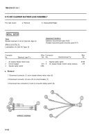
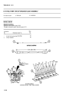
Connector
Wire
No.
Electrical Lead To:
No.
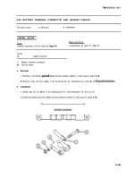
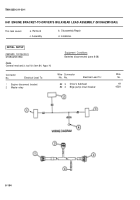
1
Fuel prime switch terminal 2
76
2
Circuit breaker
76
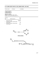
WIRING DIAGRAM
8-185
INITIAL SETUP
Equipment Conditions
Back to Top

