TM-9-2350-311-20-1 - Page 835 of 1275
TM9-2350-310-1
8-78
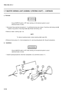
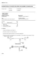
MASTER WARNING LIGHT ASSEMBLY (STEERING SHAFT) — CONTINUED
a. Removal
Ensure MASTER switch is OFF when working on hull electrical system to avoid
electrical shocks or bums.
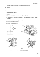
1 Disconnect three electrical connectors (1, 2, and
3)
and remove two screws (7) and two self-locking nuts
(8)
located on top portion of mounting bracket
(9).
Discard self-locking nuts.
2
Remove master warning light (10).
NOTE
To remove mounting bracket, remove steering wheel (para 9-8).
3
Remove three screws (11), three Iockwashers (12), and mounting bracket (9). Discard Iockwashers.
b. Installation
Ensure MASTER switch is OFF when working on hull electrical system to avoid
electrical shocks or bums.
1 Install mounting bracket (9), three new Iockwashers (12), and three screws (11 ).
8-190
WARNIN G
WARNIN G
Back to Top

