TM-9-2350-311-20-1 - Page 841 of 1275
TM9-2350-311 -20-1
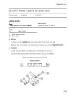
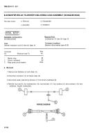
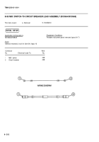
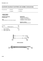
8-82 MASTER RELAY-TO-DRIVER’S BULKHEAD LEAD ASSEMBLY (M109A4/M109A5)
This task covers:
a. Removal
b. Disassembly
c. Assembly
d. Installation
Applicable Configurations
Materials/Parts
M109A4/M109A5
Lockwashers (4) (item 94, Appx G)
Tools
Equipment Conditions
General mechanic’s tool kit (item 64, Appx H)
Batteries disconnected (para 8-28)
Connector
Wire
No.
Electrical Lead To:
No.
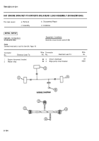
1
Master relay
82
2
Driver’s bulkhead
82
3
Bilge pump circuit breaker
452A
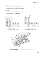
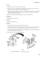
a. Removal
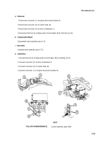
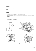
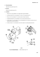
1 Remove two batteries (4) and clamp (5).
2 Disconnect connector (3) at master relay (6).
3 Disconnect power lead wiring harness (7) from driver’s bulkhead (8).
4 Remove four nuts (9), four Iockwashers (10), four washers (11), four screws (12), and connector (13) from
bulkhead. Discard Iockwashers.
8-196
INITIAL SETUP
Back to Top

