TM-9-2350-311-20-1 - Page 844 of 1275
TM9-2350-311-20-1
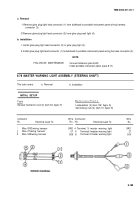
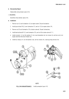
a. Removal
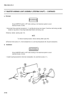
Ensure MASTER switch is OFF when working on hull electrical system to avoid
electrical shocks and bums.
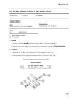
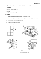
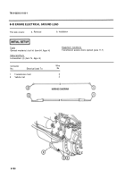
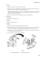
Remove two bolts (3), four Iockwashers (4), and engine electrical ground lead (5). Discard Iockwashers.
b. Installation
Ensure MASTER switch is OFF when working on hull electrical system to avoid
electrical shocks and bums.
Install engine electrical ground lead (5), four new Iockwashers (4), and two bolts (3).
NOTE
FOLLOW-ON MAINTENANCE:
Close transmission access doors (para 11 -7)
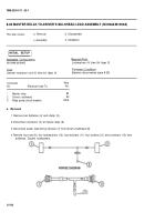
8-84 STARTER-TO-ENGINE ELECTRICAL DISCONNECT (M109A4/M109A5)
This task covers:
a. Removal
b. Disassembly/Repair
c. Assembly
d. Installation
Applicable Configurations
.
M109A4/M109A5
Tools
General mechanic’s tool kit (item 64, Appx H)
Lockwasher (item 87, Appx G)
Lockwasher (item 173, Appx G)
Lockwashers (4) (item 94, Appx G)
Equipment Conditions
Powerplant removed (para 4-5)
Materials/Parts
Electrical tape — black (item 62, Appx D)
8-199
INITIAL SETUP
WARNING
WARNING
Back to Top

