TM-9-2350-311-20-2 - Page 144 of 828
TM 9–2350–311–20–2
3–35
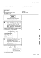
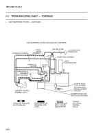
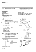
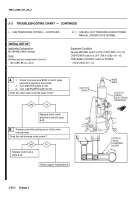
1.
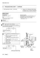
Turn MASTER and CAB POWER switches to
OFF.
2.
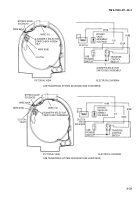
Open gunner’s selector switch box assembly.
3.
Turn MASTER and CAB POWER switches to
ON.
4.
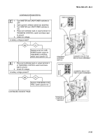
Place red multimeter lead on input terminal 2 of
TRAVERSE CONTROL switch and black lead
to ground.
5.
Check for voltage.
Is battery voltage present?
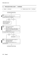
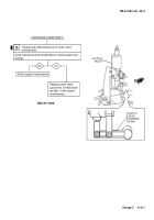
CONTINUED FROM STEP B
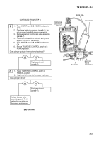
Replace wire from CAB
POWER switch output to
TRAVERSE CONTROL
switch input (para 8–12).
yes
no
C
D
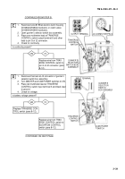
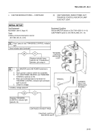
1.
Place red multimeter lead on output terminal 3
of TRAVERSE CONTROL switch and black
lead to ground.
2.
Check for voltage.
Is battery voltage present?
yes
no
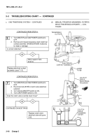
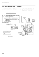
Replace TRAVERSE CON-
TROL switch (para 8–12).
CONTINUED ON NEXT PAGE
OUTPUT TERMINAL
TRAVERSE
CONTROL
SWITCH
INPUT TERMINAL
TRAVERSE
CONTROL
SWITCH
GUNNER’S SELECTOR
SWITCH BOX ASSEMBLY
+
–
GUNNER’S SELECTOR
SWITCH BOX ASSEMBLY
+
–
Back to Top

