TM-9-2350-311-20-2 - Page 146 of 828
TM 9–2350–311–20–2
3–37
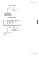
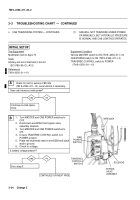
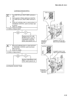
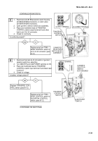
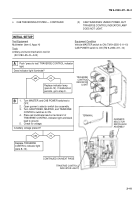
yes
no
Replace bypass valve
assembly (para 6–7). If
malfunction persists, no-
tify support maintenance.
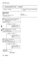
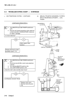
1.
Place TRAVERSE CONTROL switch in
MANUAL position.
2.
Apply a small amount of pressure to plunger.
Does plunger retract?
yes
no
Replace solenoid
(para 6–7).
Replace solenoid
(para 6–7).
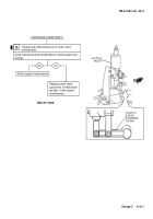
END OF TASK
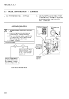
CONTINUED FROM STEP B
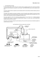
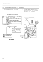
TRAVERSE
CONTROL
SWITCH
WIRE 825A
SOLENOID
BYPASS
VALVE
ASSEMBLY
PLUNGER
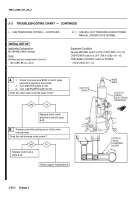
1.
Turn MASTER and CAB POWER switches to
OFF.
2.
Discharge hydraulic pressure (para 6–3). Do
not reconnect wire 645 at pressure switch.
3.
Remove solenoid from bypass valve assembly
(para 6–7).
4.
Reconnect wire 825A to solenoid and ground
edge of solenoid to valve body.
5.
Turn MASTER and CAB POWER switches to
ON.
6.
Ensure TRAVERSE CONTROL switch is in
POWER position.
Does plunger protrude from bottom of solenoid?
F
G
Back to Top

