TM-9-2350-311-20-2 - Page 210 of 828
TM 9–2350–311–20–2
3–98
Change 2
3–3
TROUBLESHOOTING
— CONTINUED
h.
CAB LIGHTING SYSTEM
— CONTINUED
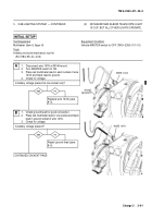
(5)
ALL CAB LIGHTS ARE OUT.
— CONTINUED
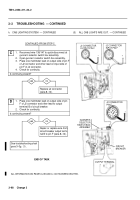
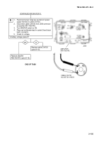
Repair or replace wire from
circuit breaker output termi-
nal B to pin F (para 8–12).
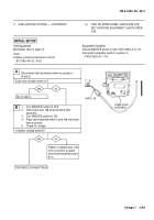
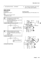
1.
Reconnect wire 138/147 to quick-disconnect at
gunner’s selector switch box assembly.
2.
Open gunner’s selector switch box assembly.
3.
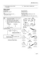
Place one multimeter lead on output side of pin F
of J2 connector and other lead on input side of
pin F of J2 connector.
4.
Check for continuity.
Is continuity present?
yes
no
C
yes
no
D
CONTINUED FROM STEP C
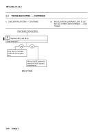
Replace J2 connector
(para 8–12).
+
GUNNER’S
SELECTOR
SWITCH BOX
ASSEMBLY
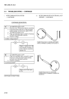
CIRCUIT
BREAKER
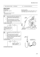
1.
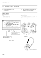
Place one multimeter lead on output side of pin
F of J2 connector and other lead to output
terminal B of circuit breaker.
2.
Check for continuity.
Is continuity present?
OUTPUT TERMINAL
See troubleshooting chart
para 3–3g. (1) .
END OF TASK
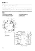
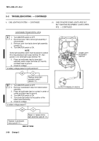
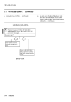
ALL INFORMATION ON PAGES 3–99 AND 3–100 HAS BEEN DELETED.
J2 CONNECTOR
INPUT PIN F
J2 CONNECTOR
OUTPUT PIN F
+
–
J2 CONNECTOR
PIN F
–
Back to Top

