TM-9-2350-311-20-2 - Page 215 of 828
TM 9–2350–311–20–2
3–103
i.
INTERCOMMUNICATION SYSTEM
— CONTINUED
(1)
INTERCOMMUNICATION SYSTEM WILL NOT
OPERATE.
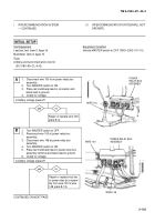
INITIAL SETUP
Test Equipment
Lead set, test (item 5, Appx H)
Multimeter (item 6, Appx H)
Tools
Artillery and turret mechanic’s tool kit
(SC 5180–95–CL–A12)
Equipment Condition
Vehicle MASTER switch to OFF (TM 9–2350–311–10)
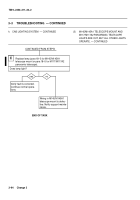
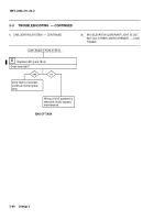
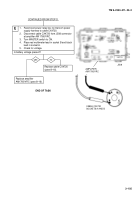
Repair or replace bus bar
in power relay box assem-
bly from wire 100 to wire
148 (para 8–13).
yes
no
A
yes
no
CONTINUED ON NEXT PAGE
B
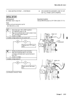
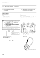
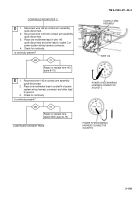
Repair or replace wire 100
(para 8–4).
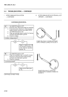
1.
Disconnect wire 100 from power relay box
assembly.
2.
Turn MASTER switch to ON.
3.
Place red multimeter lead in connector and
black lead to ground.
4.
Check for voltage.
Is battery voltage present?
+–
WIRE 100
POWER RELAY BOX
ASSEMBLY
WIRE 148
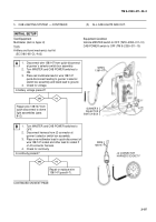
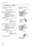
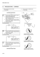
1.
Turn MASTER switch to OFF.
2.
Reconnect wire 100 at power relay box
assembly.
3.
Disconnect wire 148 at power relay box
assembly.
4.
Turn MASTER switch to ON.
5.
Place red multimeter lead in power relay box
assembly terminal and black lead to ground.
6.
Check for voltage.
Is battery voltage present?
POWER
RELAY BOX
ASSEMBLY
WIRE 100
–+
Back to Top


