TM-9-2350-311-20-2 - Page 222 of 828
TM 9–2350–311–20–2
3–110
3–3
TROUBLESHOOTING — CONTINUED
i.
INTERCOMMUNICATION SYSTEM
— CONTINUED
(3)
DRIVER CANNOT COMMUNICATE.
— CONTINUED
A
B
C
D
E
F
G
K
L
M
N
P
A
B
E
F
G
H
J
K
L
M
N
P
A
B
C
D
E
F
G
H
J
K
L
M
N
P
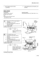
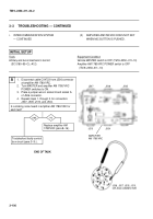
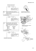
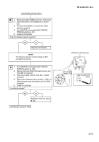
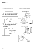
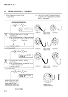
1.
Reconnect cable CX9640 connector to power
system wiring harness connector.
2.
Disconnect cable CX9640 from
telephone/intercom wiring harness connector in
driver’s compartment of hull.
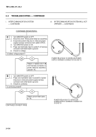
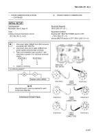
3.
Place one multimeter lead on wire 41 terminal
and other lead in socket A of telephone/intercom
wiring harness connector.
4.
Check for continuity.
Is continuity present?
CONTINUED ON NEXT PAGE
CONTINUED FROM STEP E
yes
no
F
–
TELEPHONE/INTERCOM WIRING
HARNESS CONNECTOR SOCKET A
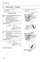
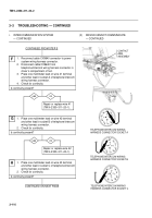
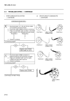
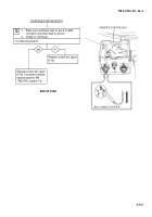
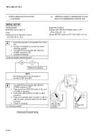
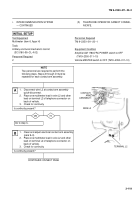
1.
Place one multimeter lead on wire 42 terminal
and other lead in socket B of telephone/intercom
wiring harness connector.
2.
Check for continuity.
Is continuity present?
G
yes
no
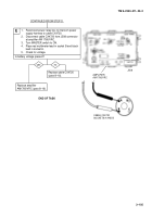
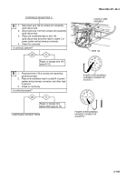
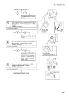
1.
Place one multimeter lead on wire 43 terminal
and other lead in socket C of telephone/intercom
wiring harness connector.
2.
Check for continuity.
Is continuity present?
H
Repair or replace wire 42
(TM 9–2350–311–20–1).
CONTACT
ARM
ASSEMBLY
TELEPHONE/INTERCOM WIRING
HARNESS CONNECTOR SOCKET B
TELEPHONE/INTERCOM WIRING
HARNESS CONNECTOR SOCKET C
Repair or replace wire 41
(TM 9–2350–311–20–1).
+
–
–
Back to Top


