TM-9-2350-311-20-2 - Page 229 of 828
TM 9–2350–311–20–2
3–117
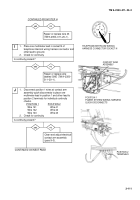
yes
no
C
CONTINUED FROM STEP B
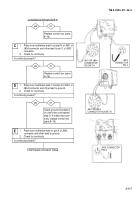
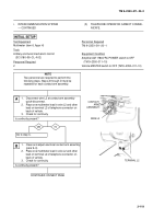
1.
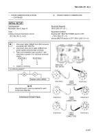
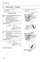
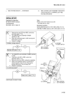
Place one multimeter lead in socket H of J801 or
J804 connector and other lead to pin C of J803
connector.
2.
Check for continuity.
Is continuity present?
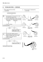
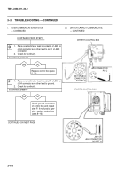
1.
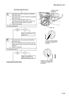
Place one multimeter lead in socket A of J801 or
J804 connector and other lead to ground.
2.
Check for continuity.
Is continuity present?
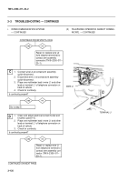
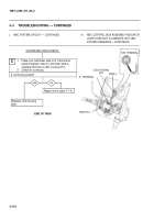
Replace control box (para
8–16).
Check ground connection
of control box and repeat
step D. If malfunction per-
sists, replace control box
(para 8–16).
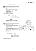
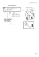
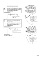
1.
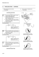
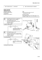
Place one multimeter lead on pin A of J803
connector and other lead to ground.
2.
Check for continuity.
Is continuity present?
yes
no
D
CONTINUED ON NEXT PAGE
E
+
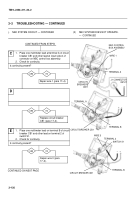
Replace control box (para
8–16).
yes
no
+
–
J803
CONNECTOR
PIN C
J801 OR J804
CONNECTOR SOCKET A
+ –
J803 CONNECTOR
PIN A
J801 OR J804
CONNECTOR
SOCKET H
Back to Top

