TM-9-2350-311-20-2 - Page 225 of 828
TM 9–2350–311–20–2
3–113
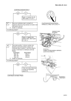
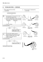
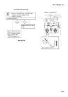
CONTINUED FROM STEP L
yes
no
M
CONTINUED ON NEXT PAGE
–
+
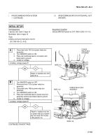
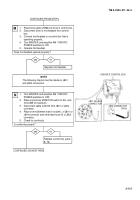
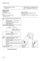
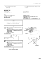
DRIVER’S CONTROL BOX
1.
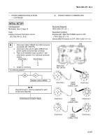
Reconnect cable CX9640 at driver’s control box.
2.
Disconnect driver’s mic/headset from control
box.
3.
Connect mic/headset to a control box that is
operating properly.
4.
Turn MASTER and amplifier AM 1780/VRC
POWER switches to ON.
5.
Operate mic/headset.
Does mic/headset operate properly?
Replace mic/headset.
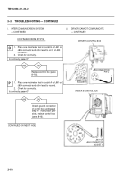
1.
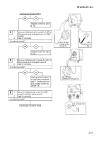
Turn MASTER and amplifier AM 1780/VRC
POWER switches to OFF.
2.
Place control box MONITOR switch to ALL and
VOLUME to maximum.
3.
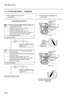
Disconnect cable CX4723 from J801 or J804
connector.
4.
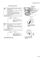
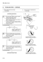
Place one multimeter lead in socket L of J801 or
J804 connector and other lead to pin B of J802
connector.
5.
Check for continuity.
Is continuity present?
N
NOTE
The following checks must be made on J801
and J804 connectors.
yes
no
Replace control box (para
8–16).
J802 CONNECTOR
PIN B
J801 OR J804
CONNECTOR
Back to Top

