TM-9-2350-311-20-2 - Page 219 of 828
TM 9–2350–311–20–2
3–107
i.
INTERCOMMUNICATION SYSTEM
— CONTINUED
(3)
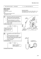
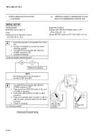
DRIVER CANNOT COMMUNICATE.
INITIAL SETUP
Test Equipment
Multimeter (item 6, Appx H)
Tools
Artillery and turret mechanic’s tool kit
(SC 5180–95–CL–A12)
Personnel Required
TM 9–2350–311–20–1
Equipment Condition
Amplifier AM 1780/VRC POWER switch to OFF
(TM 9–2350–311–10)
Vehicle MASTER switch to OFF (TM 9–2350–311–10)
yes
no
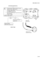
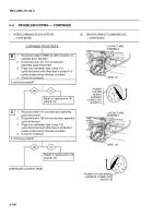
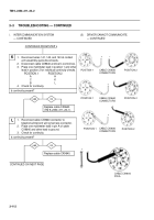
Replace cable CX9640.
A
CONTINUED ON NEXT PAGE
NOTE
Steps B through L must be repeated for each
contact arm assembly.
–
+
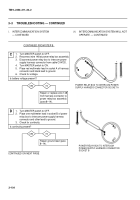
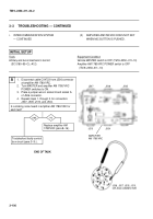
1.
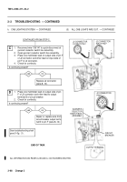
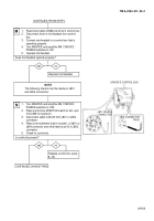
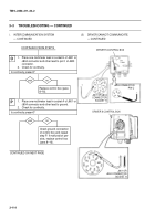
Disconnect cable CX9640 from J505 connector
at amplifier AM 1780/VRC.
2.
Disconnect other end of cable CX9640 from
power system wiring harness connector.
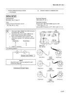
3.
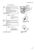
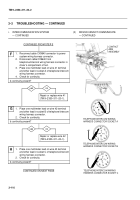
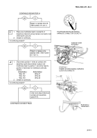
Place one multimeter lead in position 1 and
other lead in position 2 for individual continuity
checks.
POSITION 1
POSITION 2
BL
CK
AH
4.
Check for continuity.
Is continuity present?
POSITION 2
–
+
–
+
CABLE
CX9640
CONNECTORS
POSITION 1
POSITION 1
POSITION 1
POSITION 2
POSITION 2
CABLE
CX9640
CONNECTORS
CABLE
CX9640
CONNECTORS
J505
AMPLIFIER
AM 1780/VRC
Back to Top

