TM-9-2350-311-20-2 - Page 261 of 828
TM 9–2350–311–20–2
5–5
5–3
FIRING MECHANISM ASSEMBLY, M49 (M284 CANNON)
This task covers:
a.
Disassembly
b.
Inspection
c.
Assembly
INITIAL SETUP
Applicable Configuration
M109A5 howitzer
Tools
Artillery and turret mechanic’s tool kit
(SC 5180–95–CL–A12)
M34 Fuzesetter (item 1, Appx H)
Materials/Parts
GAA (item 17, Appx D)
Personnel Required
2
Equipment Condition
Firing mechanism removed (TM 9–2350–311–10)
a.
Disassembly
1
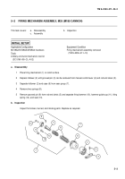
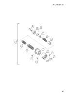
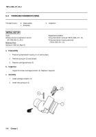
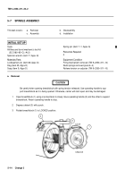
Place firing mechanism (1) on solid surface.
2
Place M34 fuzesetter over follower (2) and depress until grooved pin (3) can be removed from manual control
lever (4) and hammer guide yoke (5). Remove grooved pin and manual control lever.
WARNING
Springs are under compression. Raise M34 fuzesetter, follower, and case assembly slowly or per-
sonnel injury may result.
3
Raise and remove M34 fuzesetter, follower (2), and case assembly (6).
4
Remove two retaining rings (7) and two grooved pins (8) from case (9), if damaged.
8
7
2
3
4
6
9
1
5
Back to Top

